Engineering, 14.06.2021 06:50, deena7
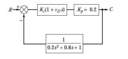
Plot the root locus diagram for the Plot the root locus diagram for the system shown in . We may consider this system to consist of a process having negligible lag; an underdamped, second-order measuring element; and a PD controller. This system may approximate the control of flow rate, in which case the block labeled K p would represent a valve having no dynamic lag. The feedback element would represent a flow measuring device, such as a mercury manometer placed across an orifice plate. Mercury manometers are known to have underdamped, second-order dynamics. Plot the diagram for t D 13 We may consider this system to consist of a process having negligible lag; an underdamped, second-order measuring element; and a PD controller. This system may approximate the control of flow rate, in which case the block labeled K p would represent a valve having no dynamic lag. The feedback element would represent a flow measuring device, such as a mercury manometer placed across an orifice plate. Mercury manometers are known to have underdamped, second-order dynamics. Plot the diagram for t D 13 .

Answers: 3


Other questions on the subject: Engineering
Engineering, 04.07.2019 18:10, keigleyhannah30
Aplate clutch has a single pair of mating friction surfaces 250-mm od by 175-mm id. the mean value of the coefficient of friction is 0.30, and the actuating force is 4 kn. a) find the maximum pressure and the torque capacity using the uniform-wear model. b) find the maximum pressure and the torque capacity using the uniform-pressure model.
Answers: 3
Engineering, 04.07.2019 19:20, rida10309
At steady state, air at 200 kpa, 325 k, and mass flow rate of 0.5 kg/s enters an insulated duct having differing inlet and exit cross-sectional areas. the inlet cross-sectional area is 6 cm2. at the duct exit, the pressure of the air is 100 kpa and the velocity is 250 m/s. neglecting potential energy effects and modeling air as an 1.008 kj/kg k, determine ideal gas with constant cp = (a) the velocity of the air at the inlet, in m/s. (b) the temperature of the air at the exit, in k. (c) the exit cross-sectional area, in cm2
Answers: 2
Engineering, 04.07.2019 19:20, dndndndnxmnc
The process in which the system pressure remain constant is called a)-isobaric b)-isochoric c)-isolated d)-isothermal
Answers: 3
Do you know the correct answer?
Plot the root locus diagram for the Plot the root locus diagram for the system shown in . We may con...
Questions in other subjects:


Mathematics, 06.12.2020 09:20
Mathematics, 06.12.2020 09:20

Chemistry, 06.12.2020 09:20
Mathematics, 06.12.2020 09:20
Mathematics, 06.12.2020 09:20

Physics, 06.12.2020 09:20
Mathematics, 06.12.2020 09:20